
Heat Pipes: aka Magic Pipes
Jane Baumann
In my previous blog on thermosiphons, I introduced a multipart blog on two-phase heat transport devices. With this blog, I would like to introduce you to heat pipes (sometimes written as “heatpipes”).
A heat pipe is a hermetically sealed pipe, typically lined with a porous sintered metal (wick), and containing a small mass of a working fluid. The pipe material and working fluid are chosen based on their compatibility (non-reactivity) and the expected operating range for the device. Copper/water and aluminum/ammonia are common pairings of materials and working fluids.

Heat Pipe Mechanism (graphic courtesy of Zoolatures)
When heat is applied to the outside of one end of the pipe, heat travels through the wall into the wick where fluid in the wick is vaporized. Due to slight pressure differentials caused by the temperature gradient along the pipe, vapor flows to the cold end of the pipe where it condenses. The condensate then flows back to the warm end through the wick structure via capillary forces, where the cycle is repeated. There is often no designated evaporator or condenser: you can have multiple hot or cold spots along the length, and the heat pipe will automatically work to isothermalize them.
The heat pipe is considered one of the most efficient means to transport heat loads over long distances without the use of power or pumps.
Brief History of the Heat pipe
Heat pipes evolved from two-phase thermosiphons. In 1942, R. S. Gaugler patented the concept of adding a capillary structure inside a thermosiphon (patent 2350348) to assist the return of liquid from the condenser to the evaporator for a refrigeration unit. However, the concept was not developed beyond the patent level.
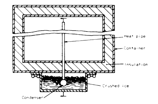
Gaugler's Concept of a Refrigeration Unit Using a Heat Pipe
Twenty years later, the nuclear physicist George. M. Grover developed the first working model of a heat pipe while researching how to use a nuclear reactor to generate electricity at the Los Alamos National Laboratory. He coined the term “heat pipe” in his 1966 patent for an “Evaporation-condensation Heat Transfer Device” (patent 3229759). His patent, although similar to Gaugler’s, provided a theoretical analysis of the heat pipe performance. For many years the terms thermosiphon and heat pipe were synonyms. Over time they became distinguished by the presence or the lack of a wick structure. Grover’s work was the launching point of a flurry of heat pipe development during the 1960’s.
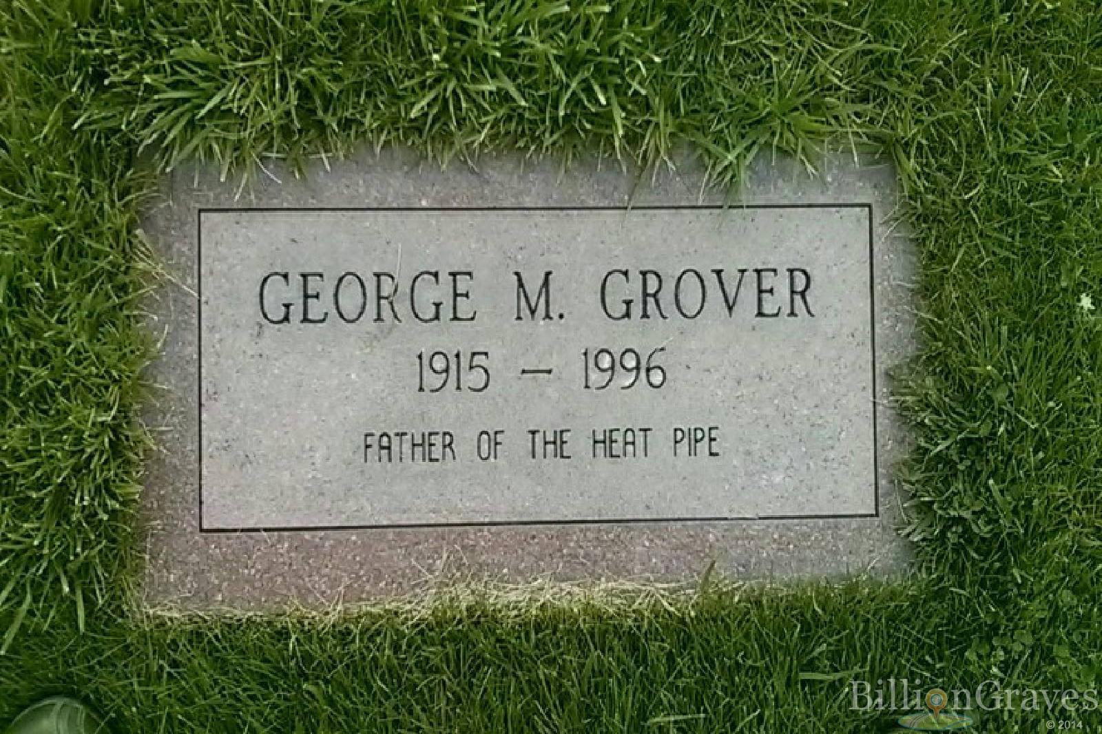
George M. Grover Grave Site, Father of the Heat Pipe
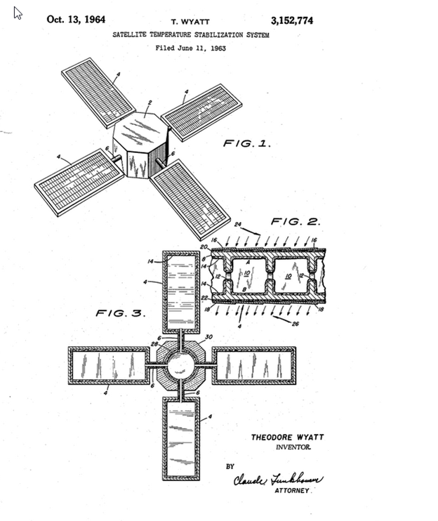
With the addition of an internal wick, heat pipes could now work in a zero-g environment in addition to being able to pump the condensate (to some degree) uphill against gravity. Theodore Wyatt (U.S. Patent US3152774 A) proposed the use of heat pipes for space applications, specifically for the temperature control of solar arrays. For this system he proposed screen-lined flow channels integrated within the structure of each solar array, with all the arrays structures being interconnected by a central reservoir. Wyatt later introduced the concept of using a non-condensable gas to block the condenser, inventing an important tool: a variable conductance heat pipe (VCHP). By contrast, without a gas to “turn down” heat through-put, the previously described devices are considered to be constant conductance heat pipes (CCHPs).
Since the early 1960s, heat pipes have become commonly used in many industries for transporting heat over long distances and for isothermalizing. Their usage has expanded beyond nuclear and space applications to include applications such as electronics cooling, engine and oil cooling, solar thermal, waste heat recovery, and biomedical. Your laptop most likely has a heat pipe inside of it, as do some cell phones and perhaps even your car.
Heat pipes in Today’s World
The miniaturization of electronics over the last 40 years has resulted in a surge of further heat pipe development bringing new ideas to market such as pulsating heat pipes, flat plate, arterial pipes, rotating heat pipes, vapor chambers (also called vapor chamber fins), and micro heat pipes. Heat pipe development eventually lead to the development of capillary pumped loops and loop heat pipes in the 1980s (fodder for an upcoming blog post).
Today there are many types and configurations of heat pipes available. Here are a few of them with brief descriptions on how they work. Perhaps you will find one of these useful in your next design.

Laptop Heatpipe (photo atributed to Kristoferb at English Wikipedia)
Constant (fixed) Conductance Heat pipes (CCHP)
These devices are the traditional heat pipes: basically a pipe with some type of internal wicking system which can be based on sintered metal, screens, or axial grooves on the interior of the pipe wall. Plus, of course, a small amount of pure two-phase working fluid. The CCHP is a passive device and is capable of transferring heat with no means to control or throttle the power flowing through it.

Heat Pipe Cross Section, Sintered Metal Wick (photo atributed to Epbernard (Own work))

Spacecraft Axial Grooved Heat Pipe (photo atributed to BillAnderson71 (Own work))
When working with a CCHPs there are a few key design limits you must consider:
- The pipe centerline should be constrained within a single plane for operation in a gravity environment, or at least the heated sections cannot be tilted far above that plane. This is the reason that any tilt above that plane is called the adverse tilt.
- One limit on thermal power transport is the capillary limit, also known as the circulation limit. Basically, the small pressure lift that the capillary meniscus provides is a budget that can be spent either on frictional pressure losses (mostly due to liquid flow within the wick) or on pumping liquid against gravity.
- Another transport limit is the entrainment limit: short-circuiting of the liquid return flow. When vapor velocities are too high, fluid droplets can be stripped off of the wick or the channel surface by shear forces. If this happens those droplets are swept back to the condenser without having passed through the evaporator first.
- Yet another transport limit is the sonic limit: choked flow at the evaporator outlet. This limit can occur in start-up of a liquid metal heat pipe (using perhaps sodium or potassium as a working fluid) from a frozen state.
- And still another transport limit exists: the vapor pressure limit. In some ways, this really is just another way in which the capillary budget can be spent. The often-negligible vapor flow losses can become significant at cold temperatures (near the triple point). In other ways, the vapor pressure limit can cause loss of isothermality as the temperature changes associated with that pressure drop (along the saturation line) are themselves no longer negligible. Like the sonic limit, this is often a concern when starting a liquid metal heat pipe from a frozen state.
- The final classical heat pipe limit is the burn out limit or boiling limit. This is a limit not on heat transport, but rather on heat flux on the evaporator. When fluxes are high enough, bubbles form within the wick rather than on its free surface. These voids impede liquid circulation, quickly using up that capillary budget. They degrade heat transfer as well.
- For CCHPs, a key degradation mechanism is non-condensable gas (NCG) generation. A build-up of NCG over time can occur due to manufacturing contamination or other impurities, resulting in gas blockage in the condenser. While that gas blockage is a feature of VCHPs, as we’ll shortly see, it is trouble in a pipe not designed for any NCG.
The good news it the heat pipe manufacturer will consider these limits when designing a heat pipe for you.
The bad news is that their design will only be as good as the requirements you can provide. This means that the ability to model the heat pipe in the host system is critical. You need to bound all the possible operational and mission scenarios to which the pipe will potentially be exposed, assuring that you have adequate design margin.
Variable conductance heat pipes (VCHPs)
VCHPs are similar in construction to CCHPs, however they generally use non-condensable gas to block a portion of the condenser in a controlled fashion. These pipes have a gas reservoir loaded with an inert gas. When the gas reservoir is heated, the gas expands into the condenser to reduce the condensing region, reducing the power through-put (often to keep the evaporator from getting too cold). VCHPs can be designed to have active or passive control of the reservoir temperature. They might have wicked or non-wicked reservoirs, depending on whether or not there is a concern for liquid getting trapped in the reservoir.
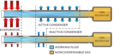
Variable Heat Pipe Thermal Management (graphic courtesy of ACT, Inc.)
If you can find a copy, the Heat Pipe Design Handbook prepared for NASA by B&K Engineering is a great resource to understand more about CCHPs and VCHPs. (Note that FCHP, or fixed conductance heat pipe, was often used interchangeably with CCHP in earlier years.)
VCHPs have similar design limits as do CCHPs: capillary limit, boiling limit, and so forth. In addition to the normal CCHP design considerations, the VCHP has the following considerations:
- Parasitic heat loss/gain on the adiabatic section of the pipe
- Requirement to cold-bias the reservoir
- Option to add temperature control to the reservoir
- Multiple gas fronts due to localized heating in a portion of the condenser, results in loss of temperature control
- Reservoir dry out, results in loss of temperature control
- Potential for reverse operation if condenser becomes warmer than the evaporator
- Ability to function as a diode heat with active control on the reservoir and sufficient gas charge
When it comes to modeling a VCHP, you can use bounding analyses for sizing purposes, but it is very important to run transient simulations: steady-state solutions are rarely sufficient. It is very common to have systems which will experience off-nominal conditions such as multiple gas fronts. Often these conditions are short-termed events, and the pipe will return to nominal operation after the excursion, but you need to make sure that your electronics, sensor, or payload can tolerate the excursion.
Although the VCHP described above may be the most common design, there are other types pipes with variable conductance available, here are a few of them.
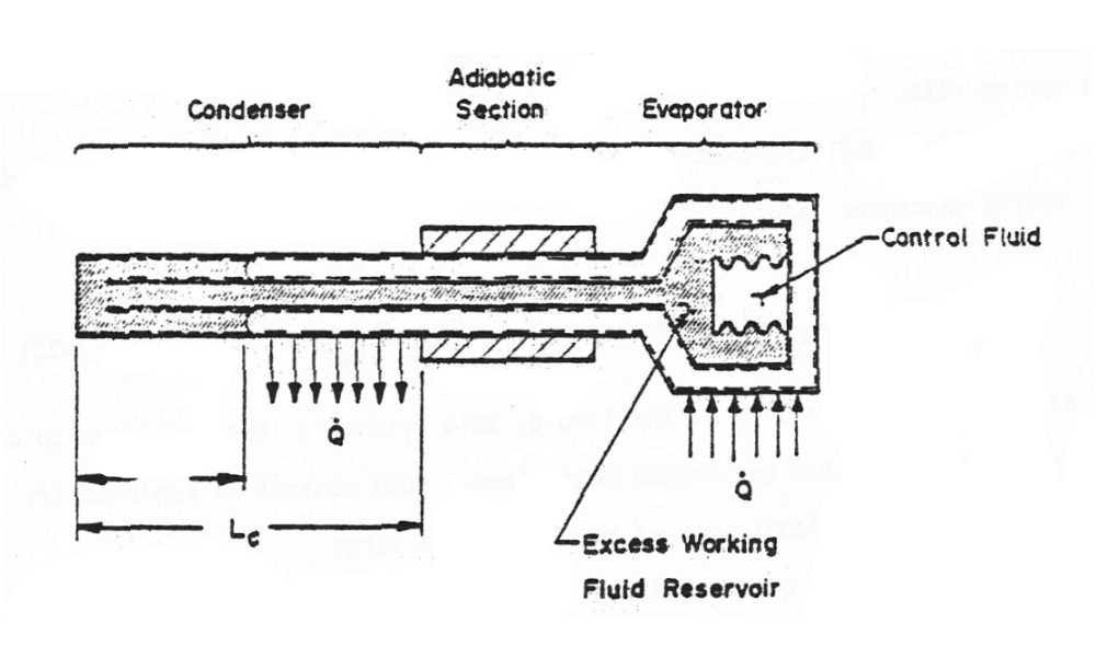
Excess Liquid Heat pipe
This concept is similar to the VCHP but instead of blocking the condenser with gas, it is blocked with excess liquid. The reservoir is placed inside the evaporator end of the pipe where a bellows controls the expansion of the fluid.
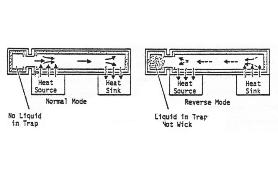
Liquid Trap Heat pipe
This concept is based on the tendency of the liquid to accumulate in the coldest part of the pipe. A reservoir placed on the evaporator end of the pipe acts as a “trap” for the excess liquid. The trap contains a wick which is not connected to the wick of the evaporator and the trap has a good thermal connection to the evaporator. During normal operation of the pipe, the trap is warm and dry. However, if the temperature profile reverses (meaning that the condenser becomes warmer than the evaporator), liquid condenses in the trap and becomes trapped due to the lack of a wick connection back to the evaporator. Without enough liquid, the transport capacity of the pipe diminishes. When the temperature profile reverses to normal operation, the good thermal connection between the trap and the evaporator allows vaporization of the liquid and a transition back to normal operation.
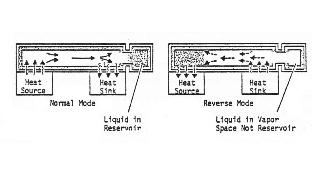
Liquid Blockage Pipe
This concept is a bit like a hybrid of the standard VCHP and the liquid trap pipe. It has a reservoir located at the end of the end of the condenser. Under normal operation the excess liquid accumulates in the reservoir and does not impact the pipe performance. If the profile reverses (condenser warmer than the evaporator) the excess fluid vaporizes and moves to the evaporator where it condenses, forming a liquid plug and stopping vapor flow to the evaporator. This concept has many design challenges with regards to minimizing the reservoir volume yet being able to block both the evaporator and adiabatic sections of the pipe.
Modeling Heat pipes
In the mid 1980s, while working in the aerospace industry, I was tasked with integrating variable conductance heat pipes into a spacecraft for battery temperature control. At that time, there were no standard built-in methods for modeling heat pipes (Thermal Desktop and FloCAD did not exist, and the only tool available was text-based SINDA). The principles for modeling a VCHP were well understood by people in the heat pipe industry, but not by the average engineer. As we quickly learned, the process was very tedious and required the manual creation of the network, plus extensive custom “user logic” to balance the partial pressures in order to track the moving gas-front (the point in the condenser between blocked and unblocked condensation). In 2001, CRTech introduced the first built-in methods for system-level modeling of heat pipes. (If I were twenty years younger my life would have been so much easier!)
You may have heard that heat pipes are easy to model, “just use a highly conductive material, or a large conductor.” Or perhaps you may have been told you need to model the full thermohydraulics of the device, including phase change, fluid flow, and liquid positioning. Before you start modeling heat pipe, I recommend you first read this brief overview on How to Model a Heat Pipe.
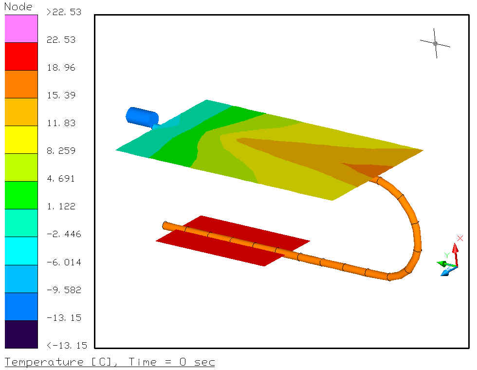
FloCAD model of a Variable Conductance Heat pipe
FloCAD’s method for modeling heat pipes is a system-level simulation of the heat pipe based on methods used for over 30 years in the aerospace industry and have been proven to be very accurate (and here is that small print: when used properly). The tool can be used to model CCHPs with or without non-condensable gas (for degradation studies), as well as standard VCHPs. Other types of heat pipes can be modeled with Thermal Desktop but they may require a more customized implementation than the built-in method.
Summary
Don’t shy away from heat pipes because you are not sure how they work or how to model them. Today there is a plethora of material on the internet about how heat pipes work, which did not exist in the 1980s. And there are modern tools for verifying their suitability to your application, and for communicating your design requirements to your heat pipe vendor or designer.
And if you find you need extra capacity or extra flexibility (both in the mechanical sense and in the design sense), you might be ready for the next step past CCHPs and VCHPs: loop heat pipes (LHPs). They will be the subject of my next blog post.