
Jane Baumann
For much of my career I was fortunate enough to work in the world of heat pipes and loop heat pipes. While working in the Aerospace industry many years ago, I would often get a phone call from a program with a thermal problem. I would walk into their office with a copper rod, a heat pipe, and a cup of hot water to demonstrate heat pipe technology by having them place the two "pipes" in the hot water so they could feel how fast the heat moved through the heat pipe to their hand. I always enjoyed their reaction; they were like 8 year olds watching a magic show for the first time. I recently went to a local community interest presentation on the Osiris Rex spacecraft where the presenter (Eric) had a small copper rod and heat pipe for demonstration. On that day, the audience was diverse, including retirees from various walks of life, but they still had that same look of awe on their faces when they tested the heat pipe. Since then I have given my collection of "magic" pipes to Eric so he can continue to inspire both the young and the old with his community presentations.
I find the evolution of a technology very interesting, but then I am a nerd. In the hopes that you also enjoy the history of technology, let me share with you the evolution of the thermosiphons, heat pipes, loop thermosiphons (LTS) and loop heat pipes (LHPs) and why these devices have influenced not only me, but also CRTech. This is the first in a multi-part blog. Future editions will cover heat pipes, LTS, and LHPs.
Part 1: Thermosiphons: Pump not Included
Heat pipes, thermosiphons, and two-phase cooling loops all have the ability to transfer large amounts of heat. The simplest of these devices is a thermosiphon (aka thermosyphon). Liquid is vaporized by heating the lower portion of a tube. The resulting vapor rises to the cooler upper portions of the tube, where it is condensed. The dense condensate falls back to the lower portion of the pipe, where the cycle repeats. Due to the large latent heat of the working fluid and to the nearly isothermal core, this device can transfer larger amounts of heat with much less temperature drop than can solid material. Since thermosiphons are gravity assisted, they can transfer these large heat loads over several meters.

Thermosiphons have an inherent diode operation since they rely on gravity (or some other acceleration or body force). Liquid pools in the bottom section. This means that if heat is applied to the top end of the pipe, no vaporization can occur since that section of pipe is "dry". Other than by conduction along the wall, no heat will be transported downward. This feature made the thermosiphon a natural choice for permafrost cooling on the Trans-Alaskan Pipeline for soil temperature stabilization. In this application, 120,000 thermosiphons were integrated into the support legs of the pipeline. These pipes were fabricated from carbon steel with ammonia as the working fluid and were up to 23 meters in length. In the summer when the air is warmer than the soil temperature, the pipes do not function. In the winter when the air is cooler than the soil, the pipes help to maintain a constant soil temperature on the legs by eliminating heat in the moving oil from entering the support legs and working its way into the permafrost, potentially destabilizing the pipeline.

Alaskan Pipe Support Legs with Integrated Thermosiphons
Photo by and (c)2005 Derek Ramsey (Ram-Man) (Own work) [GFDL 1.2], via Wikimedia Commons
Let's look back at the history of thermosiphons. In the early 1800’s Jacob Perkins developed a single-phase thermosiphon for use in central air heating systems. Piping was fed through stoves in the lower level of a building and then routed to the upper rooms. As the air warmed, it would naturally rise due to buoyancy and then drop back to the lower level to be reheated. I can't imagine this warming a room very much compared to today's HVAC systems, but I am sure it was better than nothing. Perkins also developed a single phase LTS which later became the basis for a circulating boiler, the first closed loop hot water heater. He eventually experimented with two-phase water hermetic tubes and eventually patented them in 1836. His son Angier March Perkins continued the family trade and developed what is now referred to as the "Perkins Tube" which was later patented by his son Ludlow Patton Perkins.

Single Expansion Tube for Central Heating

Perkins Boiler for Hot Water Heating
The Perkins tube became commonly used over the next 100 years in sugar refining evaporators and steam boilers. Over time, modified versions of the Perkins tube became the basis of a steam-actuated rapid-fire machine gun during the Civil War, portable baking ovens for the British army, and as fire box superheaters in locomotive boilers. Prior to 1945, closed-loop thermosiphons were also used for cooling internal combustion engines in automobiles and farm equipment, such as John Deere's MT tricycle tractor.


As time continued, the technology was applied to more applications such as:
- geo-thermal building HVAC
- geo-thermal power generation
- solar thermal (solar hot water heating)
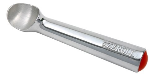
Zeroll even patented an ice cream scoop using a heat transfer fluid to transfer the heat from your hand to make the scoop slide smoothly through the cold, creamy dessert we all crave.
In the early 40s, the idea of adding an internal wick structure to a thermosiphon was patented by R. Gaugler of General Motors. However, the technology was dropped until the early 60's when George Grover, working for Los Alamos Laboratory, coined the term "heat pipe." But heat pipes are a whole new topic which will be the focus of my next blog in this series.
In 2001 CRTech added the ability to easily model heat pipes in our software. In this case it was a simple thermal-only method which captures the energy and pressure balance on the heat pipe. These methods allowed fast system-level modeling of constant and variable conductance heat pipes and have been heavily used over the years by many of our customers. However, thermosiphons are a different beast and require full thermohydraulic modeling methods. We've had such detailed methods from the start, but hadn't spent much time explaining how to use them for thermosiphons or their cousins, loop thermosiphons (LTS). There was never much demand from customers. But we do have a few folks here in the company who see this as a challenge, and who have a soft spot for two-phase transport technology, so we have developed a few sample models. For more information on thermosiphons visit our Thermosiphon web page or explore a sample model of a simple pipe thermosiphon.